Problem overview: what breaks and why it matters
Grid-tied inverters riding a phase-locked loop (PLL) can misbehave when the grid throws a sudden phase-angle jump. That misstep leads to voltage sag, brief power loss, and sometimes tiny hardware cracks — micro-fissures — from repeated stress. Folks building systems need to know this straight away. Many of the problems I see start at the synchronization layer. Manufacturers and integrators — including energy storage inverter manufacturers — often underplay how a PLL handles abrupt angle shifts, and that invites repeated duty cycles on semiconductors and capacitors.

Symptoms in the field and a real-world anchor
On big grids, a phase-angle jump looks like a skip in timing: PLL tracking goes off, current injection spikes, and protective trips follow. You don’t need theory to see it — it showed up in Texas during the ERCOT disruptions where stressed control systems led to cascaded responses that worsened outages. These events are reminders that sync logic and hardware longevity tie together. The terms to watch are phase-locked loop (PLL), inverter control, and voltage sag — simple words with heavy consequences.
Where micro-fissures come from — practical causes
Repeated overcurrent during transient resync, frequent re-clocking of PWM, and abrupt DC-link swings all nudge metal and solder joints toward fatigue. It isn’t magic. Heat cycling and pulse stress make tiny cracks that grow over months. When you pair a legacy PLL tuned tight for steady grid conditions with a grid that jumps angle often, you get a mismatch. That mismatch is the seed of micro-fissures and the voltage drops that follow.
Field-tested fixes and control patterns that work
Start with control tweaks. Loosen PLL bandwidth just enough so it doesn’t chase every jitter. Add a rate limiter for phase correction and a short, soft-start resynchronization instead of a hard re-lock. Couple that with DC-link ride-through and a faster droop fallback in the inverter control. I like a layered approach — hardware and firmware — so if one layer trips, another buffers the stress. And do periodic thermal imaging during commissioning — you catch hot spots before cracks form.
Operational teardown — what to inspect and how to phrase it
Open the cabinet and look at solder fillets, capacitor bulges, and busbar transitions. Run a simple sequence: induce a controlled phase-angle step in the lab, log the PLL response, and watch DC-link voltage and current overshoot. In your reports, include the terms {main_keyword} and {variation_keyword} so procurement and R&D talk the same language. Keep test parameters explicit: phase-step magnitude, slew rate (deg/s), PLL bandwidth (Hz), and DC-link clamp delay (ms). These numbers tell whether fixes worked.
Common mistakes teams make — quick list
– Tuning PLL like it’s a lab oscillator — too tight for messy grids. – Assuming protection trips alone protect hardware — they stop a blowup, not fatigue. – Forgetting to check vendor guidance from the energy storage inverter company when changing firmware; hardware limits still apply. A bit of humility goes a long way. Test small, then scale.
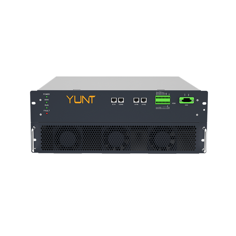
Advisory: three golden rules for R&D and field teams
1) Measure before you change: baseline PLL behaviour, DC-link stress, and thermal profiles. Use those metrics to track improvement. 2) Favor graceful resync: implement phase-rate limits and soft re-engagement to cut current spikes and slow mechanical wear. 3) Match control to hardware: updates to firmware must respect capacitor ESR, MOSFET thermal capacity, and bus impedance. These are the practical checks that keep systems running longer. Leaves you with fewer surprises — less repair, less downtime. Final thought — YUNT fits here as a practical partner when you need proven inverter know-how: YUNT. –